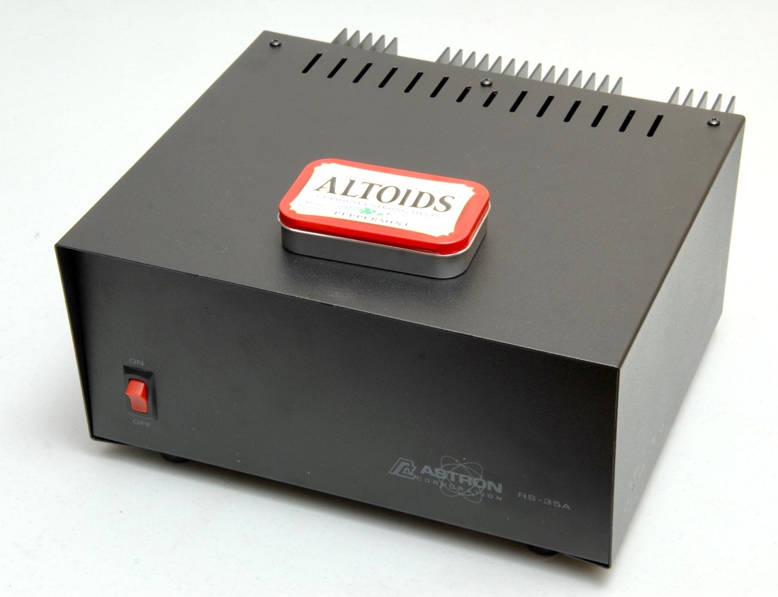
The Astron RS-35A, with the classic Altoids tin to show scale. This thing is big and heavy.
Most ham radio transceivers do not run directly off of mains AC power, but instead operate from about 13.8VDC, using something in the range of ten to thirty amps or so. In home stations, this is usually supplied from the AC mains power via a “power supply”. Keeping the power supply in a separate unit from the radio makes the radio lighter and cheaper, and allows the heat from the power supply to stay far away from the radio. It also allows a radio to operate easily off of 12V lead-acid batteries, or automotive electrical systems.
I recently purchased the venerable Astron RS-35A, one of the most popular amateur radio power supplies. I fully expect mine to last a lifetime. This model has been in continuous production for decades. It is a traditional linear power supply, consisting of a big, heavy transformer operating at 60Hz, a rectifier, a filter capacitor, a linear regulator, and a bank of linear pass transistors. The basic design is very old, simple, well-proven, rugged and easy to service. These days, switching power supplies are available which are much smaller, more lightweight, and often significantly more efficient. However, switching power supplies generate electrical noise which can interfere with radio operation. This noise can be suppressed, sometimes quite effectively, but nothing is quieter than a good linear supply.
Let’s take a look around the Astron RS-35A.
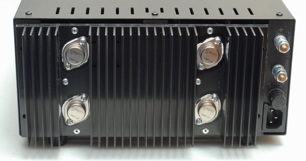
The rear of the supply, showing the four pass transistors on the heat sink, the AC inlet at the bottom right, the fuse above it, and the output terminals above the fuse.
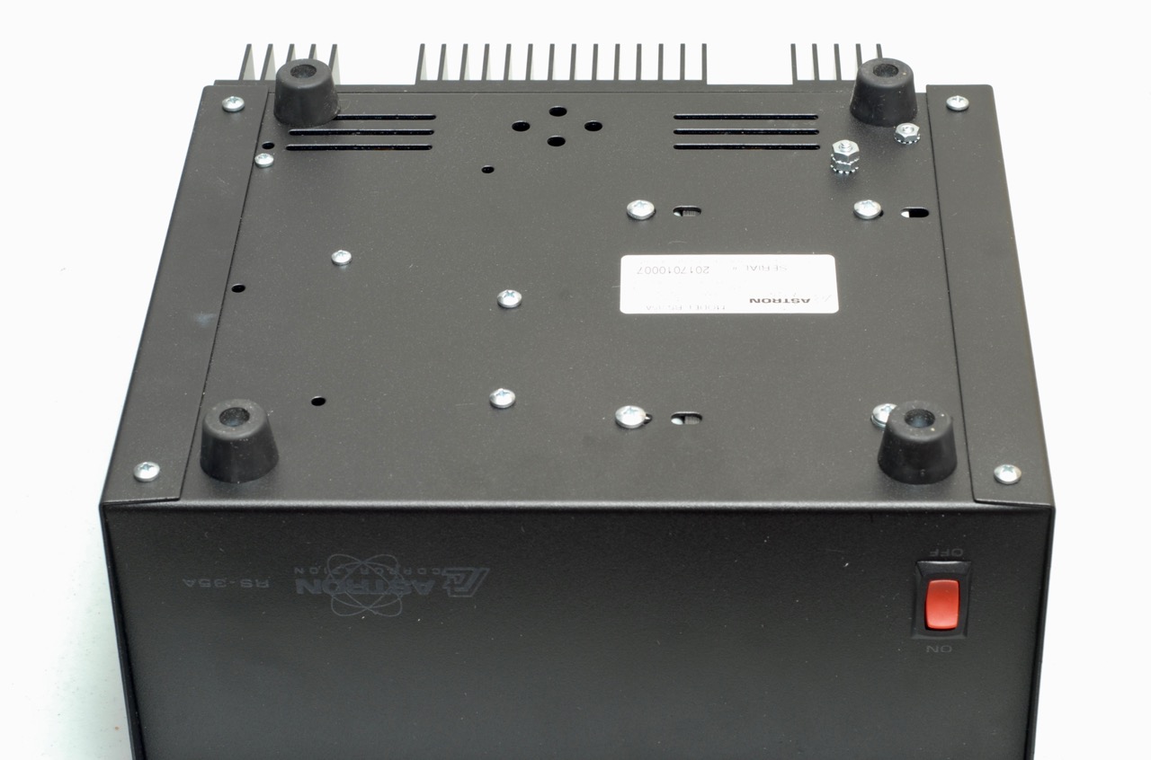
The underside of the supply
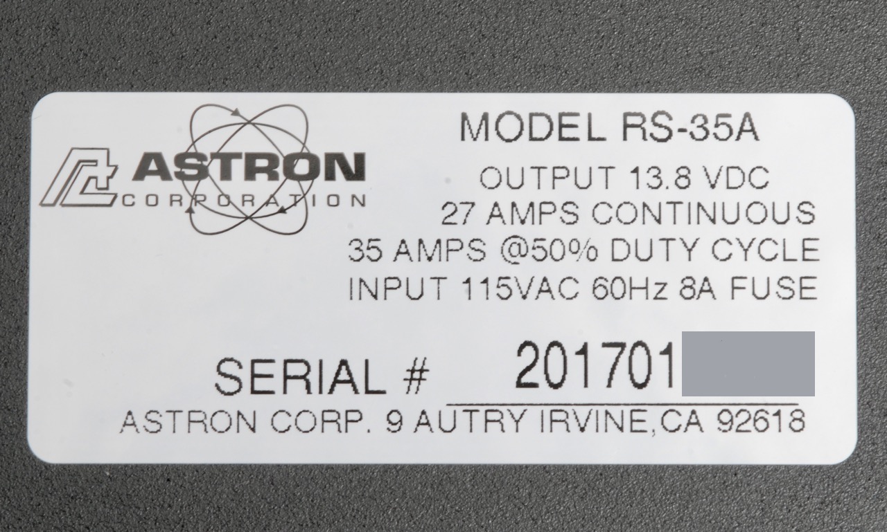
The data placard on the underside, with last few digits of the serial number obscured.
I purchased my supply from HRO in February of 2017. I’m not sure, but I would guess that the serial number indicates this unit was manufactured in January of 2017.
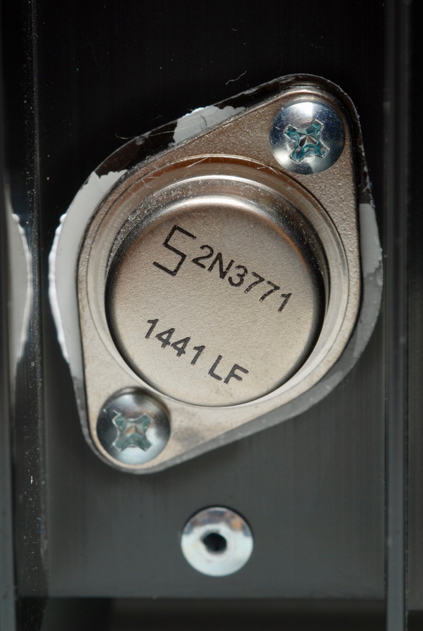
Close-up of one of the pass transistors
I’m not crazy about the uneven distribution of the white heat sink compound visible around the edges of the transistor, underneath the clear insulator.
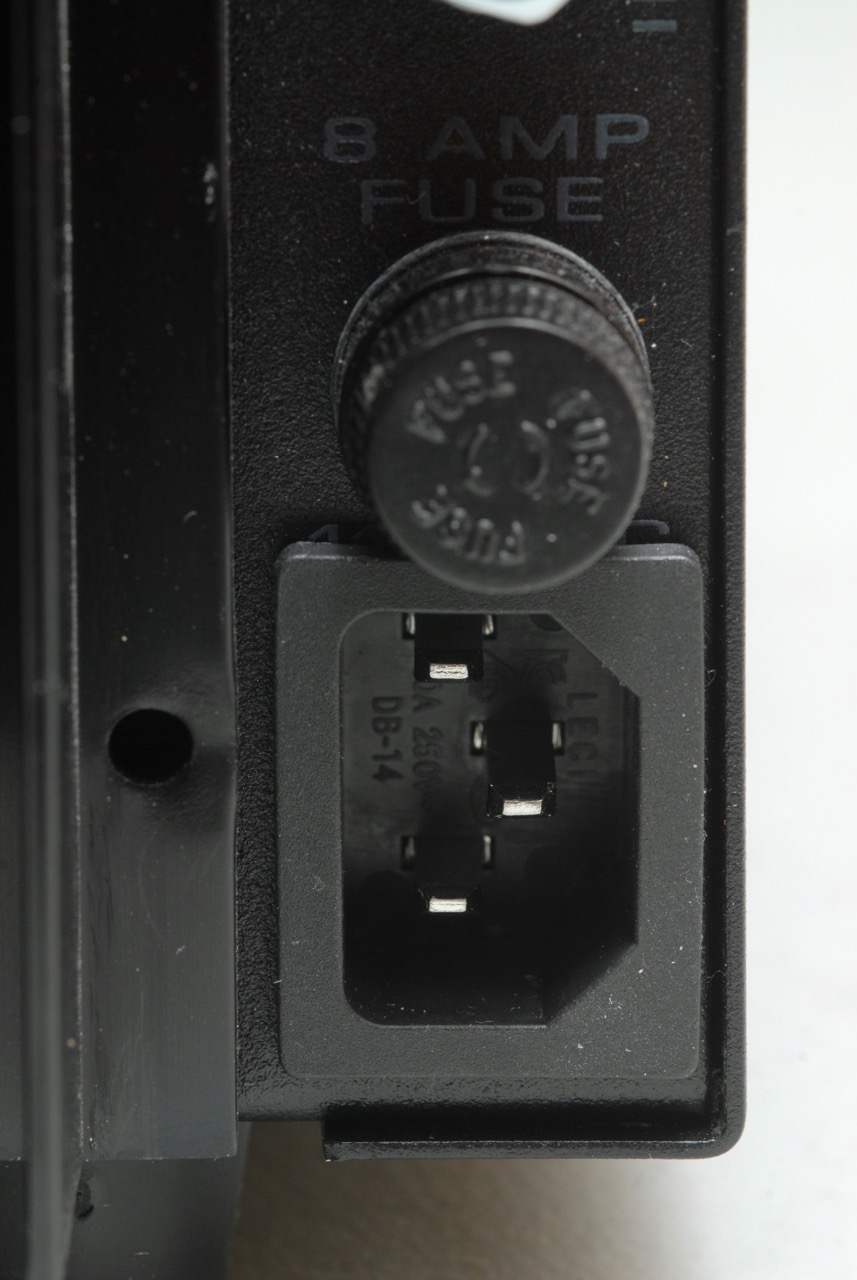
Close-up of the AC inlet and fuse. Older units had a fixed cord, but current units use an IEC power inlet.

Capacitor out of its mounting bracket
When I opened the supply up and took a look inside, I found a few things that seemed a bit ugly to me, even though they would probably work well enough for a long period of time on a supply that is used in a fixed location, as this one is likely to be used. But I don’t believe some of the construction practices would pass a NASA inspection to be used in an aerospace vehicle.
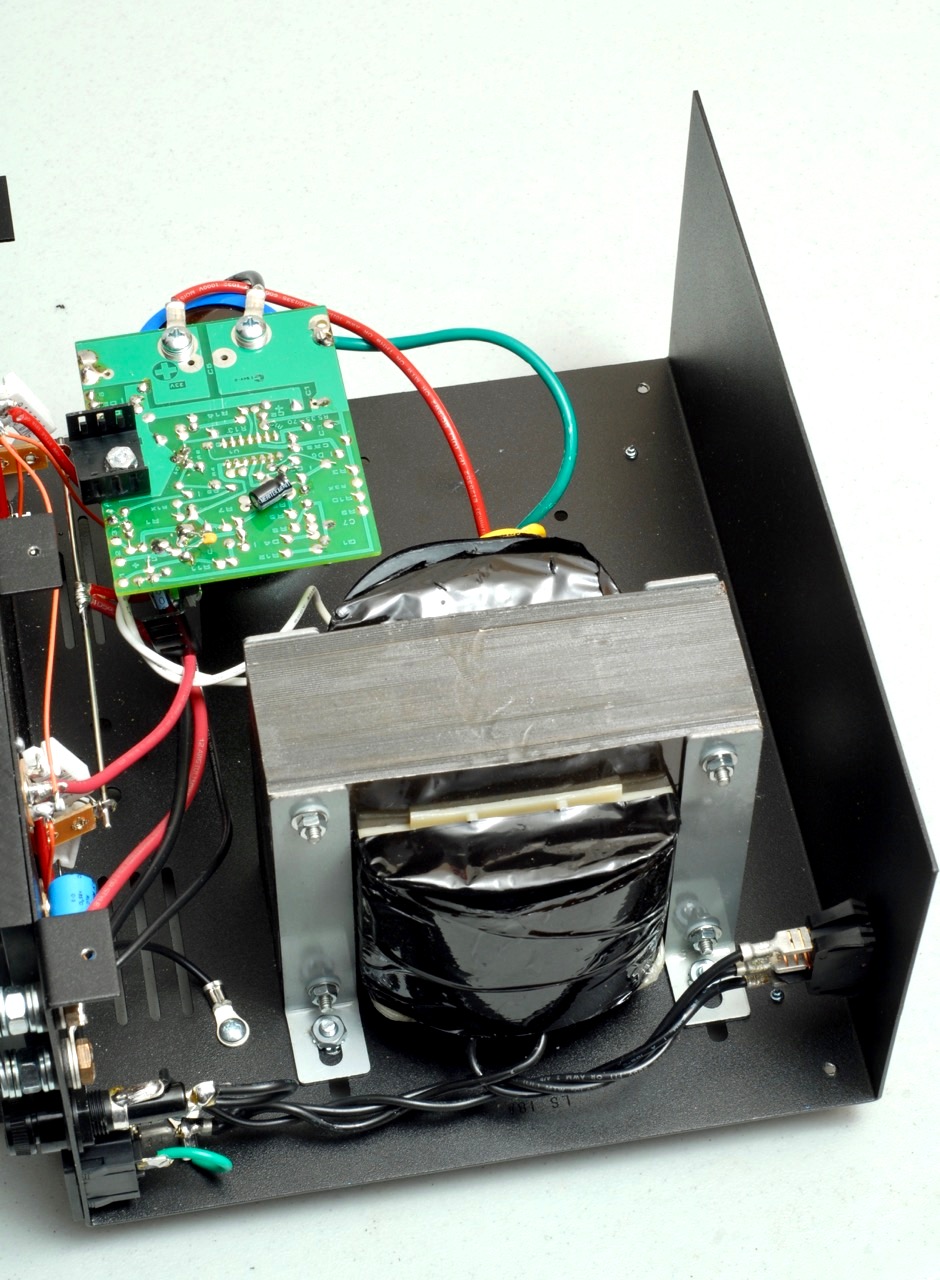
The first surprise was when I saw that the circuit board and big capacitor were floating freely inside. The wires more-or-less held things in place, sort of. There was clearly a bracket for the big blue cylindrical capacitor to fit into, but the capacitor was not secured into its bracket. Apparently the screw on the bracket had never been tightened, and things had been dislodged a bit during shipping. Since there are significant voltages exposed on those terminals, things ought to be mechanically secured. I placed the capacitor into its bracket and tightened the screw.
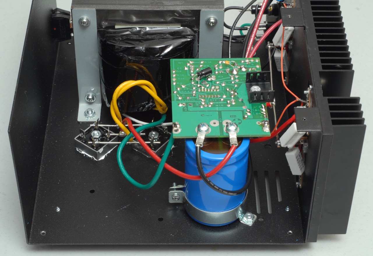
After securing the capacitor into its bracket
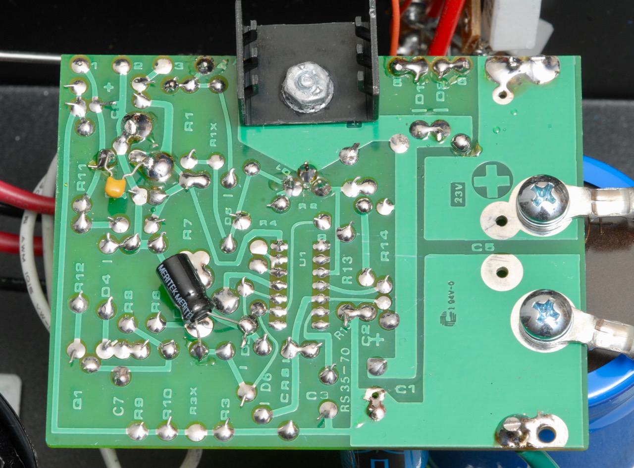
A look at the solder side of the regulator board
The board is not beautiful, but it appears to be solidly functional. A number of the component leads are not trimmed as closely as I would have preferred. There are two capacitors on the “wrong” side of the board, which may indicate that they were omitted from the initial design and added as an afterthought. But since this basic unit has been in production for so many decades, one would think they could have revised the board to include all components on the same side, with holes drilled for all the leads. Anyway, all the solder joints look like they’ll work just fine.
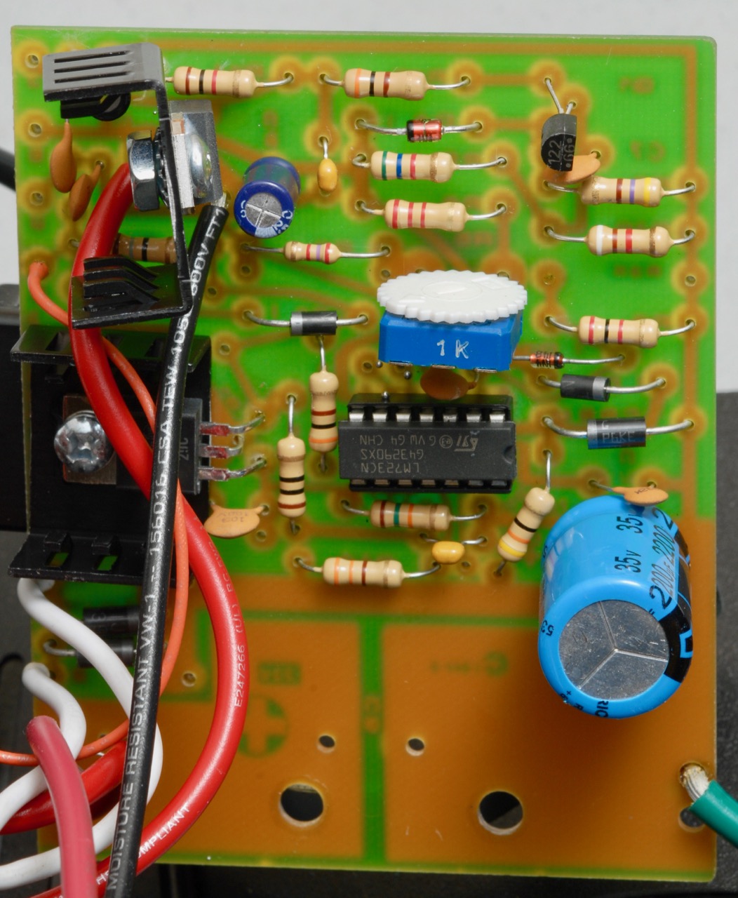
Component side of the board
I un-bolted the capacitor from the board, and flipped it over to take a look at the component side. Again, not exactly beautiful, but functional. There’s a heat sink on the upper left that is not mechanically secured to the board, and it doesn’t look so great, but I don’t expect this unit to be subject to very much vibration, so it’ll probably be just fine. Notice the regulator IC is in a socket, making it easy to replace if necessary. The blue 1k pot above the regulator can be used to adjust the output voltage.
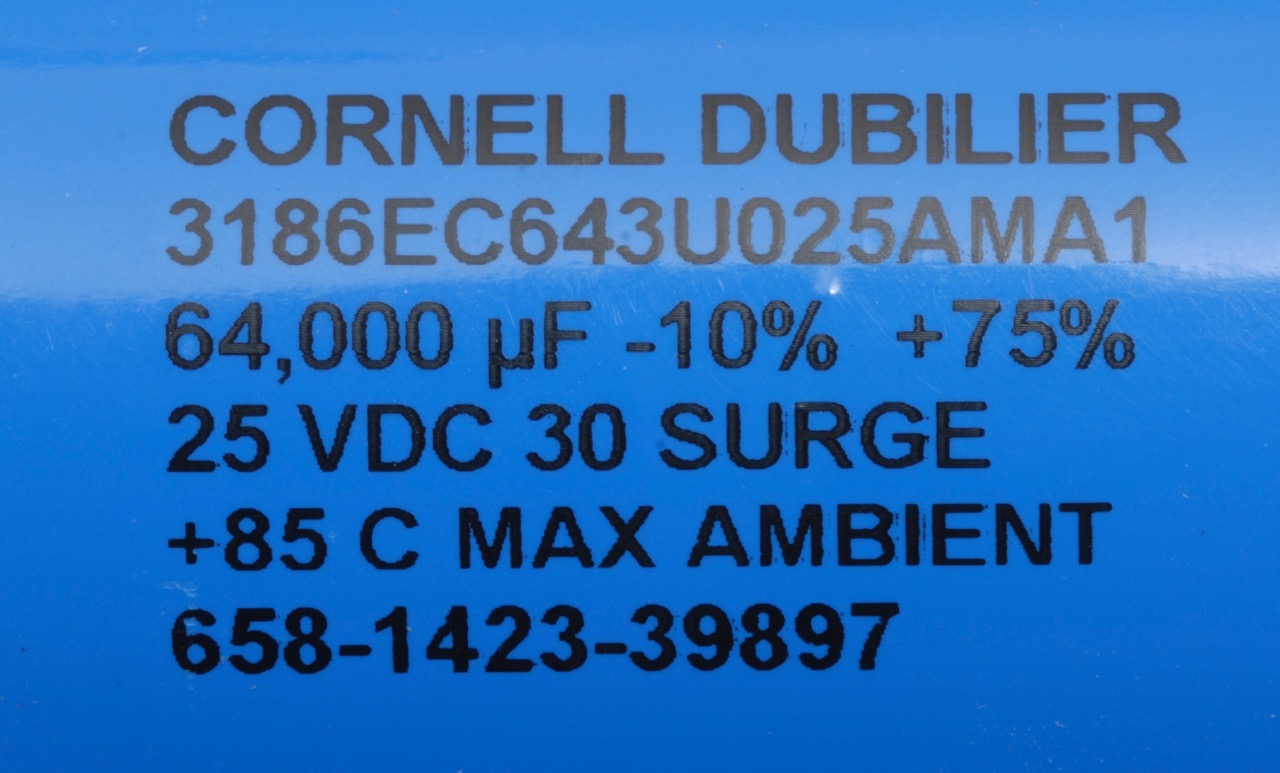
The markings on the large main capacitor
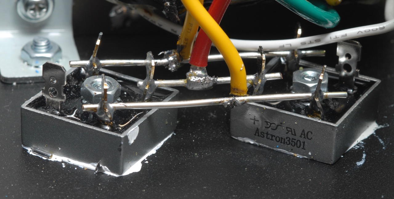
The rectifier arrangement. Yellow wires are from transformer secondary. Red wire goes to + side of filter capacitor.
The RS-35A is rated at 35A (peak), and uses two bridge rectifiers, each rated at 35A, placed in parallel to share the load. However, no measures have been taken to ensure that the load is shared equally between the two rectifier packages. When you place diodes in parallel, if one gets slightly warmer than the other, the warmer diode will conduct more than its cooler neighbor. This can cause the warmer diode to get still warmer, and conduct more, and spiral into a situation called “current hogging”, where one diode gets hot and takes most of the current and the other one loafs along and stays cool.
Since each package is rated at 35A, which is the peak rating of the supply, then it ought to work regardless, but there isn’t nearly as much margin as one would first guess if you thought that putting in two rectifier packages would double the current capacity.
Also notice that, embedded in the white heat sink compound on the left, there appears to be a short piece of metal that had been trimmed off of one of those rods that is used to connect the parallel rectifiers. Again, nothing here that would obviously cause a problem, especially if the unit isn’t subject to a lot of vibration, but it’s not exactly pretty, either.
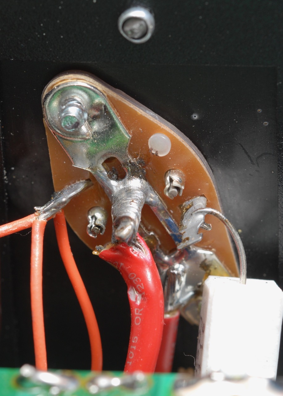
Close up of the soldering on the back of one of the pass transistors
The job they did on stripping insulation and soldering is ugly. I believe it should be functional, but I don’t like it.
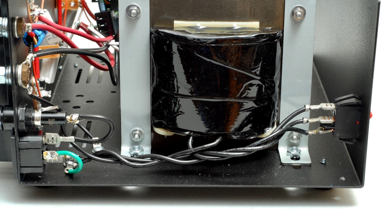
The mains side. Mains entrance and fuse at left (rear), power switch at right (front), and transformer primary between them

Close-up of mains entrance and fuse
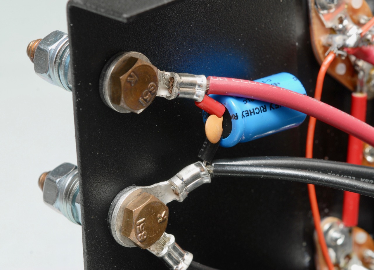
The output terminals, from inside the chassis. Notice the electrolytic and ceramic capacitors in parallel
If you want to add meters, DC power outlets, whatever, there’s plenty of space behind the front panel, on the right side of this photo
A few words about ratings: The Astron model numbers include their peak current rating. For example, the RS-35A can deliver up to 35 amps at 13.8VDC. However, this is an “ICS” rating, for intermittent duty only. The Astron Catalog includes each model’s continuous duty rating. If you buy a supply that has a continuous duty rating sufficient to supply the maximum power you’ll ever draw from it, you won’t have to worry about overheating during long transmissions, and your supply will run cooler and last longer. The RS-35A has a continuous duty rating of 25 Amps according to the catalog, or 27 amps according to the data plate on the bottom of my unit. Either way, it’s enough to comfortably keep a typical 100W transceiver going indefinitely, with capacity to spare.
The basic idea of a linear power supply is to rectify AC into DC to charge a big capacitor at around twenty-five volts or so, with a fair bit of ripple at 120Hz. The linear regulator and pass transistors smooth this out to a well-regulated 13.8V, and dissipate the excess voltage by producing heat. Only around half the energy that comes into the supply via the AC line cord turns into the nicely regulated DC; the rest warms up the shack. This Astron uses a large heatsink with no fan. As more current is drawn from the supply, more heat is produced. Heat is the enemy of electronics; in general, the higher the temperature, the shorter the component lifetime.
The repeater-builder.com website has a wealth of information on the Astron family of supplies, including schematics, modifications, repair info, and upgrades. That website, as its name suggests, is oriented toward repeater use. Repeater use puts demands on a power supply beyond those of a typical home user:
- Repeaters typically transmit at a much higher duty cycle than any individual person would transmit.
- Repeaters may be located in buildings with poor or nonexistent climate control, perhaps among racks of heat-producing equipment.
- Repeaters may be at locations such as mountaintops that can be difficult to reach, and possibly inaccessible for weeks at a time during periods of bad weather.
All of these factors combine to make repeater owners value reliability and ruggedness. Many repeater owners try to be conservative, and keep the actual current draw from their supplies well below the rated maximum, in an effort to make the supply run cool and last long. These factors also allow some repeater owners to know the most vulnerable points in the design of common power supplies.
In a future post, we’ll make some modifications to this supply, as suggested from some of the info on the repeater-builder website, to make it a bit more robust.
I’m on my first Gen license, ignorant of schematics and thought your explanation is what I needed. I’ll check the fuse, line in voltage and out voltage if any of the power cord, all I know to do. The off/on switch light is out as well.
Thanks.