Most ham radio operators know that switching power supplies found in many modern electronic devices can produce lots of radio interference. I knew this, but I tended to think of the problem as mostly one for HF. Since HF was working reasonably well for me, I assumed I didn’t have any bad noise sources, and I could mostly ignore the issue for VHF/UHF repeater use. I was wrong.
I had installed a simple 2m FM station at home, a Yaesu FT-2900 connected to a rooftop J-pole, for use with local repeaters. I live in somewhat of a bowl, surrounded by ridges. My local club’s repeater is on the top of one of those ridges, and is visible from my house, only about five miles away as the crow flies. Of course my station worked very well with this local repeater, but with other repeaters, I noticed it was something of an “Alligator”, meaning it was all mouth and no ears. People would give me excellent signal reports, indicating that I was reaching the repeater with full quieting, but I could barely copy them. I thought maybe my receiver front-end was performing poorly, but I didn’t investigate it too thoroughly, since I could use the local club repeater very well. I just limited myself to the most local repeaters.
But one evening, I was in my car, close to home, and heard a distant station on 146.52 simplex. I pulled into my driveway, and the station disappeared. I drove about two or three houses down from my house, and the station was audible again. Pulled into my driveway, and it was gone. So I switched the radio from FM mode to AM mode, at the same frequency, and drove around the block. In AM mode, there was a strongly audible noise generator, mostly hissing, but with some 120Hz hum present. And it was strongest right in my driveway.
I continued the investigation using my old handheld Icom R2 scanner in AM mode. The noise was audible all around the house, and all across the 2m band. I went to the fusebox and turned off all the power to the house. Noise was instantly gone. A little trial and error determined that the noise was coming from a branch circuit that fed the garage outlets, as well as a few outlets in the room next to the garage. I turned off and unplugged things one-by-one, and couldn’t get rid of the noise. I thought I had disconnected everything on that circuit, but then I looked up at the garage wall and noticed the doorbell transformer. I disconnected the output wires from the doorbell transformer, and the noise disappeared!
But it wasn’t the doorbell. It was a light which I had installed a few years ago. I live in a dark section of my block, far from the nearest streetlight, and years ago, before I got my ham license, I wanted to add some illumination to my house numbers.

I installed a little 3W Malibu LED floodlight, intended for outdoor landscaping use, and mounted it under the eave above my house numbers at the corner of my garage. It provided just enough illumination to draw attention to the house numbers and make them easily readable from the street. This light was designed to operate off of a 12VAC transformer for landscape lighting, but the doorbell transformer worked equally well. I liked the visual effect, but I couldn’t put up with the RF effect.
I disconnected the light, and found a whole new world of 2m repeaters and simplex operation opened up!
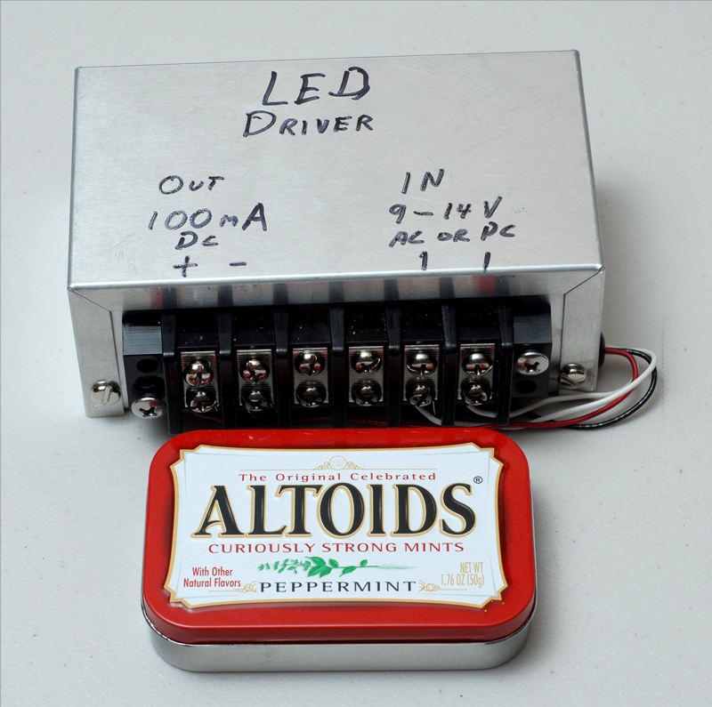
So how should I bring the light back, without bringing the noise back? Build a linear regulator! I dissected the LED lamp fixture, removed its regulator, and connected the wires directly to the LED. As you may know, LEDs requires a (more-or-less) constant current source — a voltage source will not work well. So I went to my junk box, found an LM317 regulator plus a few passive components, found a nice aluminum chassis to perform double duty as an enclosure and a heat sink, and created this:

The Altoids tin is there merely to provide a size reference.
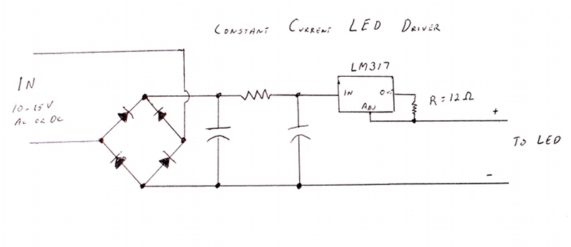
It’s a textbook regulator circuit, with a bridge rectifier, followed by a couple of capacitors and a resistor to smooth the ripple a bit, topped off with a linear regulator IC. But instead of using the regulator to create a constant voltage, I use it to get constant current. This is described on the LM317 Data Sheet (fig. 14, p 12). I feed input power to the “IN” terminal of the LM317, and take output from the “ADJ” terminal. A resistor is connected between the “OUT” and “ADJ” terminals, but the OUT is not connected to anything except this resistor. Nothing in the regulator circuit connects to ground.

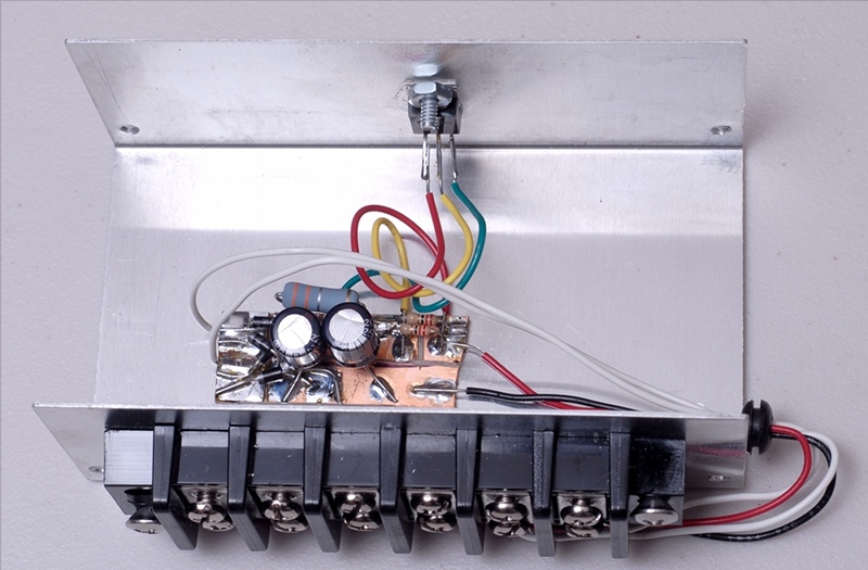
I used a crude but effective prototype construction technique of taking copper clad PCB board, and using a Dremel to cut slots in the copper plating, separating the board into “islands” of copper. Then I soldered the components to these islands.

Result: This produces a nice steady 100mA or so over a wide range of input voltages. It works perfectly from the doorbell transformer. It generates very little heat. Dissipation is around 1.5W or so, and you can scarcely feel that the regulator IC is warmer than ambient. Best of all, it makes no radio interference whatsoever! The light is a little dimmer than the original switching regulator, and that was by design. I didn’t need as much brightness as the original had, and I preferred to reduce power consumption and extend the LED lifetime by not driving it hard. The original switching driver was giving around 350mA of current, while I selected my resistor to give about 100mA.
After completing this, my wife remarked that she is now able to hear her favorite FM broadcast stations on the car radio when she’s parked in our driveway — she never mentioned to me that she had a reception problem before! Also, my daughter noticed that her clock radio gets much better reception of FM broadcast stations. So the old LED had been causing more problems than I knew.
While my noise is much improved now, I can now notice another noise source, which had previously been covered up by the switching noise from this light. Stay tuned for another episode, where I will attack the next noise source.