Inverters are devices that take DC power as provided by the electrical system of a car, truck, RV, or a standalone battery, and produce AC power, capable of running appliances designed to run on household power from a commercial utility. When choosing an inverter, you may have heard of “Modified Sine Wave” or “Pure Sine Wave” type inverters. What is the difference, aside from cost? Which makes more efficient use of battery power? Why would you prefer one over the other?
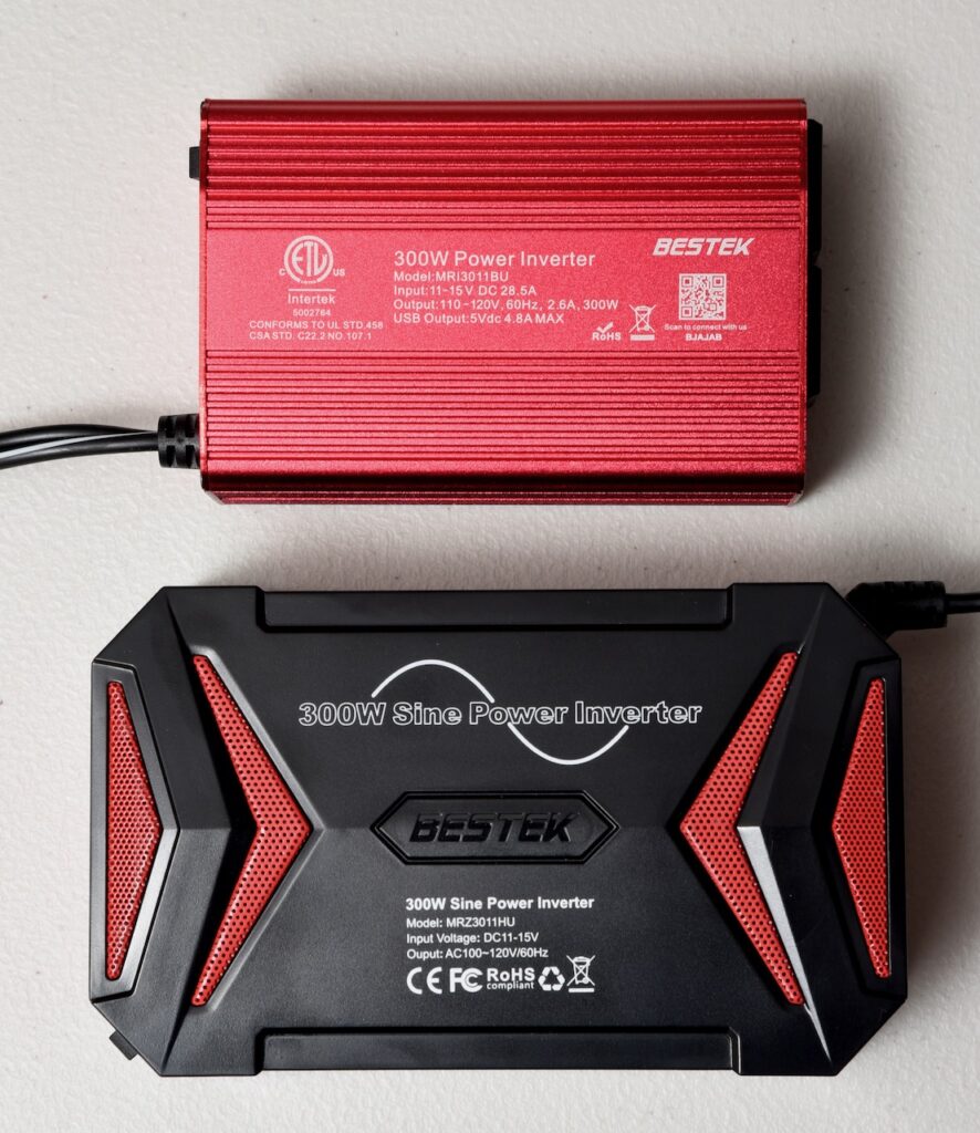
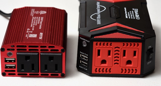
To do some comparisons, I purchased a pair of inexpensive inverters online. I chose the “BESTEK” brand, because they are common, inexpensive, and they have two 300W models which are very similar. I chose the pure sine wave model MRZ3011HU and the modified sine wave model MRI3011BU.
We’ll start with some pictures from an oscilloscope, an instrument which displays a graph of voltage versus time. Here is the voltage output of a “Pure Sine Wave” inverter when driving an incandescent light bulb:
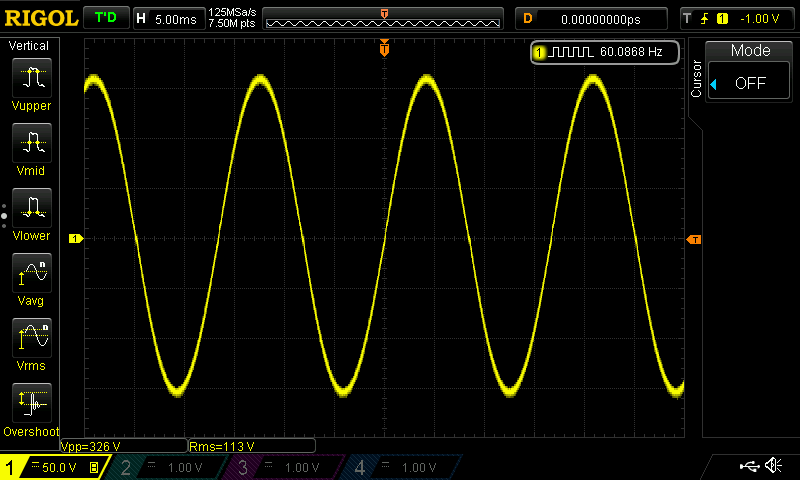
This smooth yellow curve is very similar to what you would see from a utility company’s power supply to a house. In the upper right, you can see a measurement of the frequency at 60.0868 Hz, very close to the nominal 60Hz of utility power in the USA. The bottom left shows an RMS voltage of 113V, slightly lower than the nominal 120V of utility power, but easily within tolerance.
And here is the same oscilloscope measuring the output of a “Modified Sine Wave” inverter powering the same incandescent bulb:
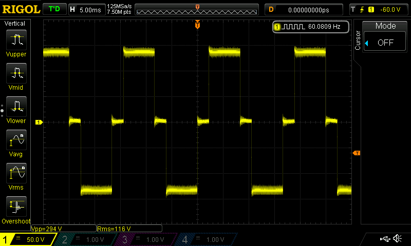
The voltage graph is anything but smooth. It goes up to a high voltage (approximately +140V), stays there for a while, goes down to near zero Volts for a short time, then goes down to a low voltage (approximately -140V) for a while, goes back to zero, and repeats the cycle. If you look a bit more closely, you see that the voltage is never quite steady, but the trace is always “fat”, indicating that the voltage is jiggling up and down slightly at a very high frequency even while it’s overall fairly flat (the pure sine wave also has a bit of high frequency noise on it, but not as much). You also can notice that each “flat” section has a little overshoot and curving section on the left side. But finally, notice that the frequency is 60.0809Hz, while the RMS voltage is 116V, very similar to the corresponding numbers from the sine wave. In fact, the RMS voltage is a little closer to the nominal 120VAC of utility power in the USA.
The marketing departments call this wave a “modified sine wave”, but that’s a lie. They did not start with a sine wave and modify it to produce that stepped wave. They basically generate three voltages, the high, middle, and low, and periodically switch the output between them. In this posting, I’m going to call this a stepped wave from now on.
The sudden voltage transitions in the stepped waveform are not good for transformers or motors. They will cause the windings of a transformer or motor to make audible noise. This noise is caused by the sudden change in voltage causing a sudden change in magnetic field produced by the windings, and the sudden change in magnetic field causing actual mechanical vibration that can be heard. Look up “Lorentz force” and/or “Laplace force” for some theoretical background if you dare. While these sharp transitions can cause issues for motors and transformers, a simple load like an incandescent light bulb can accept this waveform with no problem whatsoever.
The stepped wave form is cheaper to generate than the pure sine wave. In the 300W family of BESTEK inverters, the pure sine model is about 160% the price of the stepped wave version at the time of this writing. The pure sine model is also bigger and heavier.
When I searched the web, I saw that much of the marketing literature claimed the pure sine wave inverters are better for sensitive electronics like computers, while the stepped wave inverters can be used for simple old-fashioned devices, like a room ventilation fan. I’ve also seen marketing claims that pure sine waves have an efficiency advantage. However, I’m not convinced the marketing departments are giving us the whole truth.
Back in the days when the original IBM PC was first introduced, computers had transformer-based linear power supplies, and there may have been some truth to the idea that stepped wave inverters were not good for sensitive electronics. Today, most electronics, including TVs, battery chargers, laptop computers, etc. use switching power supplies, which are extremely forgiving of the input waveform. If you look at the data plate of an electronic device and see something like “Input: 100-240V, 50-60Hz”, that tells you that it has a switching power supply which is not picky about its input power, and a stepped wave inverter should power the device very well, as long as the device doesn’t require more power than the inverter can supply.
I put the two inverters to a head-to-head efficiency test, using four different load types. I tried a driving a household incandescent lightbulb of about 50 watts, a switching power supply that would take the 120V input power and convert it to 14V, and then use that to power an incandescent floodlight of around 60W, a transformer-based linear power supply that was feeding a resistor for about 6 watts, and a small room fan.
The stepped wave inverter was significantly more efficient than the sine wave inverter in every test. However, when driving the transformer-based power supply and the electric fan, the stepped wave inverter caused a squealing noise to come from the powered devices. I don’t know if that squealing indicated impending damage, but I didn’t keep the power on for long. If you have an inductive load like transformer or motor, I’d recommend using a pure sine wave inverter. But for a switching power supply, I’d recommend the more efficient (and cheaper!) stepped wave inverter.
The Numbers
My first test was to measure idle current, that is, the current drawn by each inverter when it was switched on, but nothing was plugged in to it.
| Stepped Wave | Sine Wave | |
| Current in | 0.35A | 0.90A |
| Power in | 4.6W | 11.8W |
Verdict: When turned on and driving no load, the sine wave inverter used 2.57 times as much current as the stepped wave inverter. Of course, if you’re concerned about conserving DC power, it’s best to keep your inverter all the way OFF when you’re not using it, but this gives you an idea of what the inverters will consume when driving a very small load.
Next, I powered an incandescent lightbulb, of around 50W rating.
| Stepped Wave | Sine Wave | |
| Current in | 3.84A | 4.11A |
| Power in | 50.3W | 53.8W |
| Output RMS Voltage | 115.9V | 112.2V |
Verdict: The sine wave inverter used 1.07 times as much current as the stepped wave inverter, which is a relatively minor increase. However, the sine wave inverter also delivered less voltage to the bulb. An incandescent voltage is nearly a pure resistive load, so the power consumed by it is nearly proportional to the square of the voltage. In other words, the Sine wave inverter consumed more current, while only delivering about 94% as much power as the stepped wave inverter. The light was slightly brighter when powered by the stepped wave inverter. Combining these two effects, the sine wave inverter used about 1.14 times as much current for every Watt delivered to the bulb.
For the next test, I fed the AC power from the inverter into a switching power supply, which converted it back to 13.8V, for use by a quartz halogen floodlight. No, it is not an efficient use of energy to convert DC to AC back to DC, but this was the most straightforward way I had of arranging an AC-powered switching power supply to present a consistent nontrivial load to the inverters. It’s pretty close to representative of what the switching power supply in a laptop computer or a battery charger might use. I didn’t use an actual charger or computer, because their power consumption can change significantly during use, so it would be hard to be assured of a fair comparison.
| Stepped Wave | Sine Wave | |
| Current in | 5.8A | 6.47A |
| Power in | 75.5W | 84.2W |
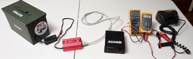
In the above photo, you can see the test setup, with a Lithium battery in the green ammo can on the left, sending 13V DC through a small power meter to measure current and voltage, into the red inverter, which sends 120VAC into the black SS-30DV switching power supply (with AG6QR stenciled on it), which sends its 13.8VDC through two meters, the bigger one on the left measuring current, and the smaller one on the right measuring voltage. Finally the power goes through some clips to the coiled cord and into the quartz-halogen floodlight on the right. I took this photo using a very bright studio photoflash, which almost totally overwhelms the light from the floodlight, especially since the floodlight is pointed away from the camera.
Verdict: The sine wave inverter used 1.12 times as much current as the stepped wave inverter. Unlike the light bulb case above, the switching power supply should be drawing a relatively constant amount of power, over a broad range of input voltages. I did verify that the DC voltage and current going from the switching power supply into the floodlight stayed consistent when I swapped inverters. As the input voltage to the switching power supply goes up, the input current required goes down, to keep the input power constant unless the load changes.
For my next test, I wanted to try a transformer-based linear supply. I used an Elenco XP-720 linear power supply, set it to produce about 14V, and connected it to a 50 ohm RF dummy load. The DC output should have been around 4 Watts, but the linear power supply is extremely inefficient.
| Stepped Wave | Sine Wave | |
| Current in | 1.28A | 1.82A |
| Power in | 16.9W | 24.0W |
Verdict: The sine wave inverter required 1.42 times as much current as the stepped wave inverter. But notice that the total power required is pretty low in either case. The absolute difference in current is 0.54A, which is very close to the absolute difference required in idling current. I’m not sure how badly the transformer-based supply was reacting to the stepped wave, but it was certainly making a noise that was not present with the sine wave inverter. Even if it might be a little more efficient, I would not recommend using the stepped wave inverter with a transformer based power supply for long term use.
As my final test, I used an electric fan, approximate diameter 14 inches, of the type used to keep cool when air conditioning isn’t available.
| Stepped Wave | Sine Wave | |
| Current in | 2.59A | 2.99A |
| Power in | 34.0W | 39.3W |
Verdict: The sine wave inverter used 1.15 times as much current as the stepped wave inverter, but as with the transformer-based supply, the fan made a noticeable squeal while running. Regardless of efficiency, I would not recommend using the stepped wave inverter with a fan, or with any other AC motorized appliance.
Final Conclusions
I didn’t have the budget to test a large sample of various sine wave and stepped wave inverters. To explore the differences between pure sine and stepped wave inverters, I picked a pair of inverters that were as comparable as I could find, the same brand name and capacity. I verified their waveforms with an oscilloscope and I tested their efficiencies. In every case, the stepped wave inverter was more efficient, with the pure sine wave inverter typically using about 15% more DC input for a given amount of AC output. This is not an enormous difference in efficiency, but it is large enough to easily measure. The only drawback I noticed to the stepped wave inverter is that it made transformers and motors produce an audible squealing noise. I didn’t notice any damage to the devices I used in testing, but I didn’t evaluate the likelihood of eventual long-term damaging effect. I do not intend to use a stepped wave inverter for any of my own personal electrical devices that use an AC motor or transformer, and I don’t recommend you use them for that, either. I believe a pure sine wave inverter is safe to use on any load within its capacity. But for powering switching power supplies, which are very common in modern electronics, the stepped wave inverter is very well-suited and efficient. It will use less input battery power than a pure sine wave inverter of similar capacity. As a bonus, the stepped wave inverter is smaller, lighter, and cheaper than the pure sine wave model.
Choose a “Pure Sine Wave” inverter if the following apply:
- If you think you may be using an inverter to power old-style transformer based devices, or appliances that use large motors. In this case, pay the efficiency penalty and get something that will be gentle on the windings in the motor or transformer.
- If ultimate efficiency isn’t so important to you. For example, if you only use your inverter in a vehicle while the engine is running and you have excess electrical capacity, the efficiency may not be so important, and the advantage of not having to worry about what kinds of loads are compatible with your inverter may justify the extra price of the pure sine model.
Choose a “Modified Sine Wave” (stepped wave) inverter if the following apply:
- If you have limited battery capacity and you want maximum efficiency for modern switching power supplies or resistive loads.
- If you’re not going to power large motors or transformers, and you want a smaller, less expensive inverter
Toss a coin if it doesn’t matter:
- If you don’t need maximum efficiency, you’re not concerned about the price difference, and you’ll only be powering loads that the stepped wave inverter handles well, like switching power supplies or incandescent bulbs.
Debunking False Advertising Claims
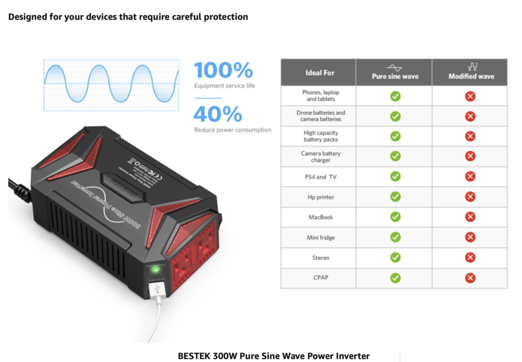
Finally, I leave you with a screenshot below of some misleading advertising for the pure sine wave inverter which I tested. There is a clear claim of “40% reduce power consumption”, when in fact, my measurements indicated a power consumption increase in every case.
There is a chart with multiple device types listed, all shown with a green checkbox for “Pure sine wave”, and a red “X” for “Modified wave”. I won’t argue with any of the green checkboxes, but for the past 25 years I’ve been using a modified sine wave inverter (an old one of a different brand, not used for these tests) to power phones, laptops, tables, drone batteries, camera batteries, high capacity battery packs, camera battery chargers, TVs, a MacBook Pro, and a Stereo. All of these devices had switching power supplies, and all worked very well with an old modified sine wave inverter. There are some items on the chart which I do not have direct experience with, so some of the red checkboxes may be warranted.