Continuing from where we left off, we’ll proceed with the assembly of the Tecsun 2p3.
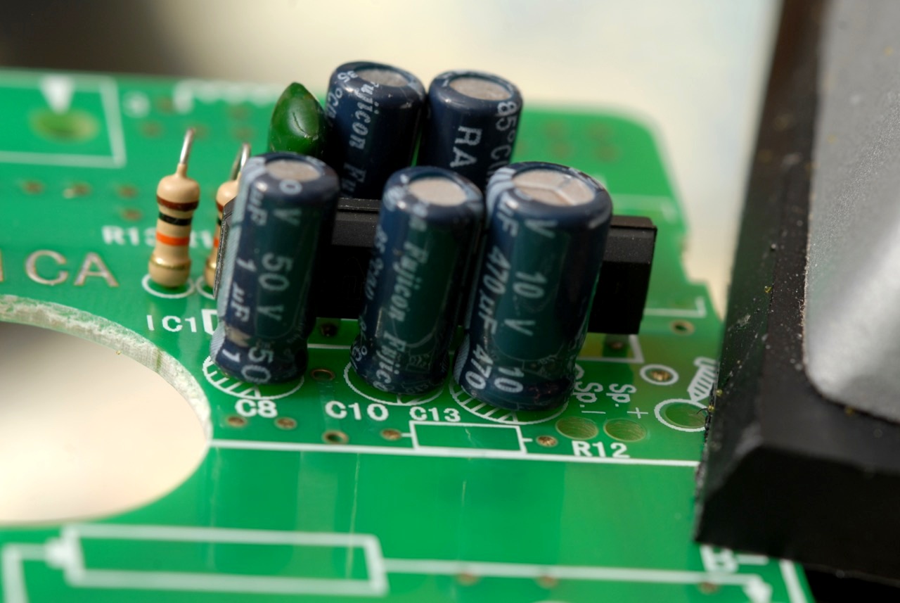
Here we insert C8, C10, and C13
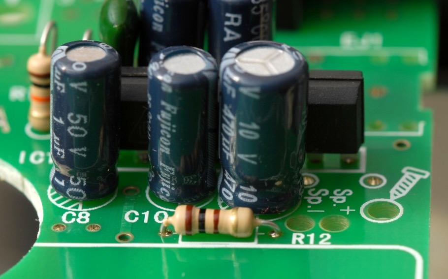
R12
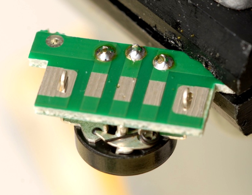
Now we solder the volume potentiometer into the broken-off piece of the circuit board. Note that we leave the end terminals unsoldered at this time.
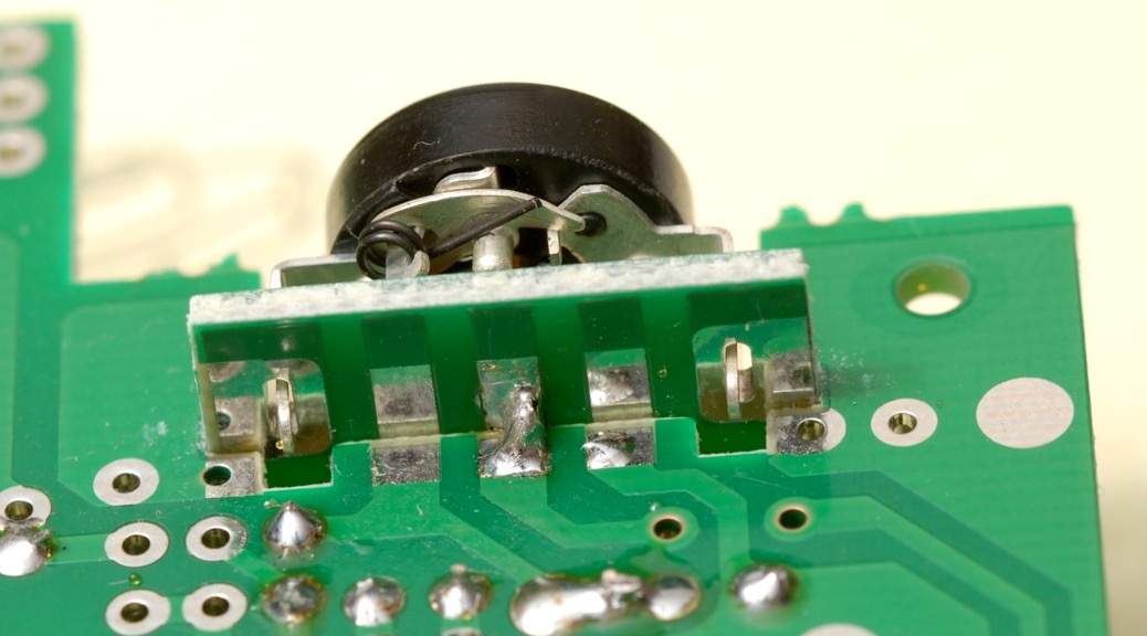
Here, we lightly tack-solder one joint between the main circuit board and the small board holding the volume pot. While only one solder joint is holding the two boards together, we can re-heat the joint and adjust the position of the small board in order to get the two boards exactly perpendicular. Play with the positioning until it’s just right.
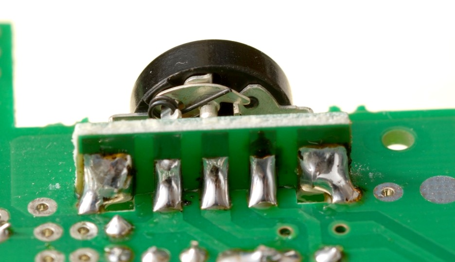
Once the positioning of the small board is perfect, go back and apply generous amounts of solder to the other joints. Finally, reheat the first joint, and apply generous solder there.
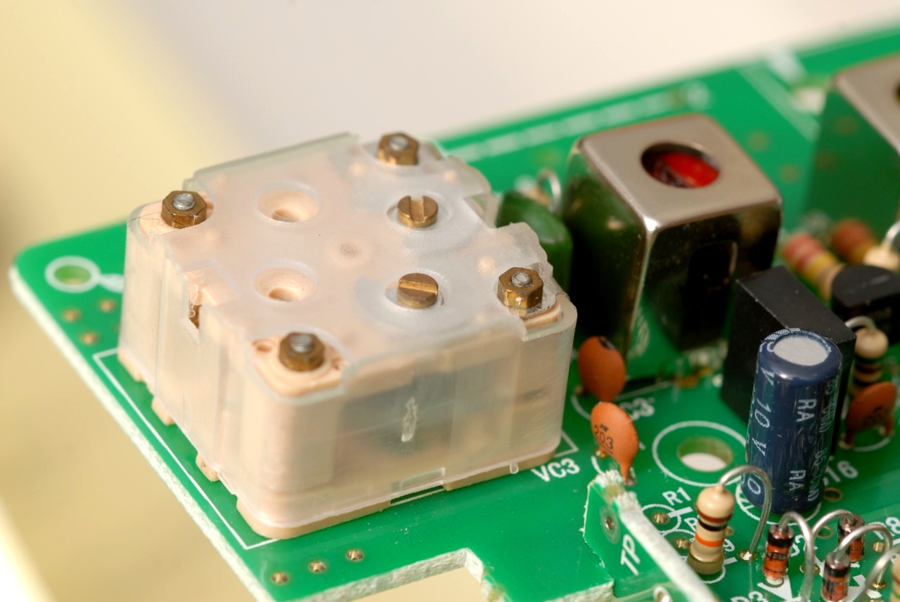
Add the tuning capacitor.
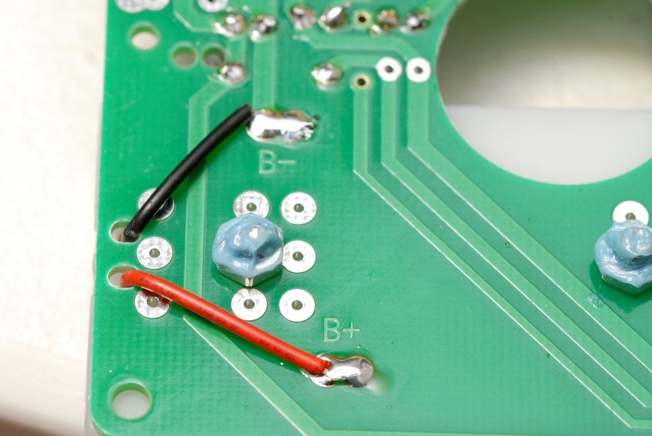
The battery holder, shown here from the underside. Notice the thread-locking compound I put on the nuts that hold the battery holder in place.
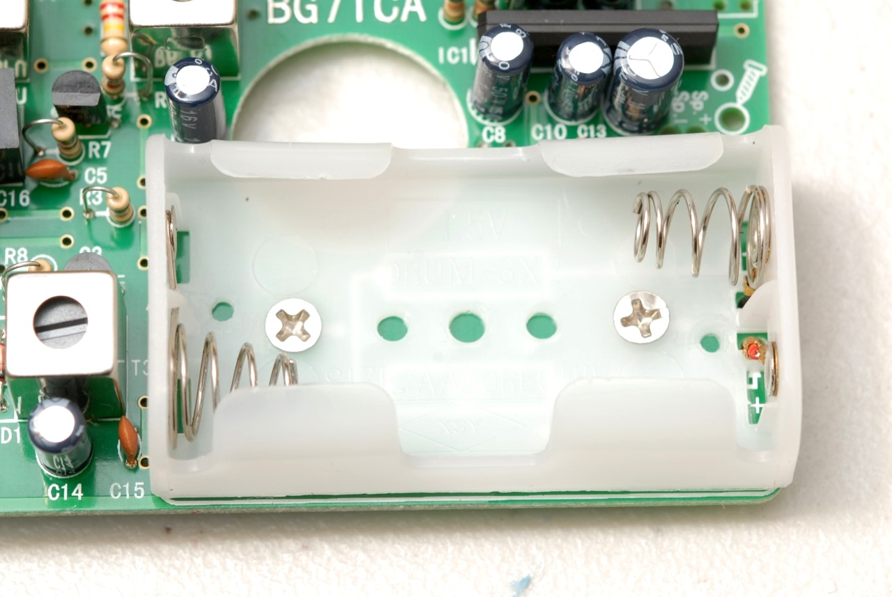
The top side of the battery holder.
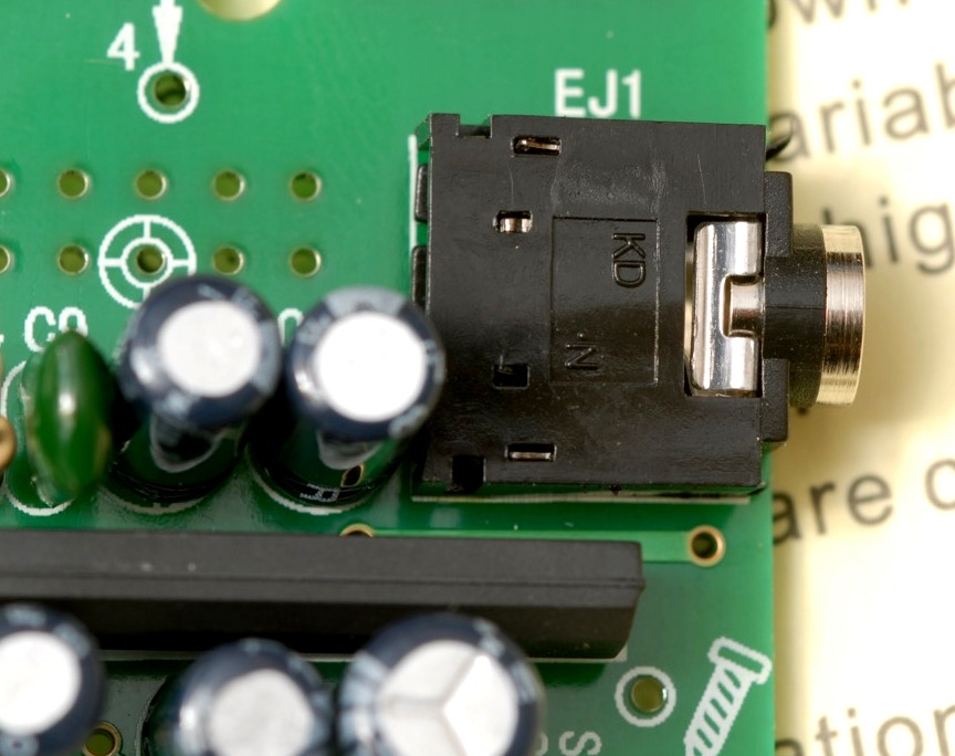
The earphone jack. Be sure it is placed flat against the circuit board before soldering. You may want to tack-solder one joint, then reheat that joint as you press it against the board, to guarantee a good fit.
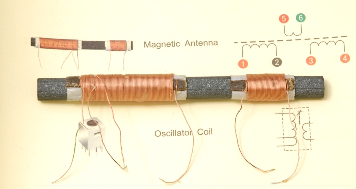
My antenna, placed on top of the picture of the antenna from the instructions. Notice that the long coil has four wires, three of which are near the end. On the photo, the long coil appears to be reversed in orientation from my sample. I didn’t realize this until after I had installed the antenna, but it is possible to slide the coil off of the ferrite bar, flip it, and make its orientation match the picture. I wish I had done that. I don’t believe it would affect performance, but the wires would have been easier to fit into the circuit board holes if I had made it match the picture.
It is difficult to see the colors on the coil wires, but the black and green are present and possible to distinguish in real life. I used an ohmmeter to double check continuity and identify wires 1 and 2, along with 5 and 6.
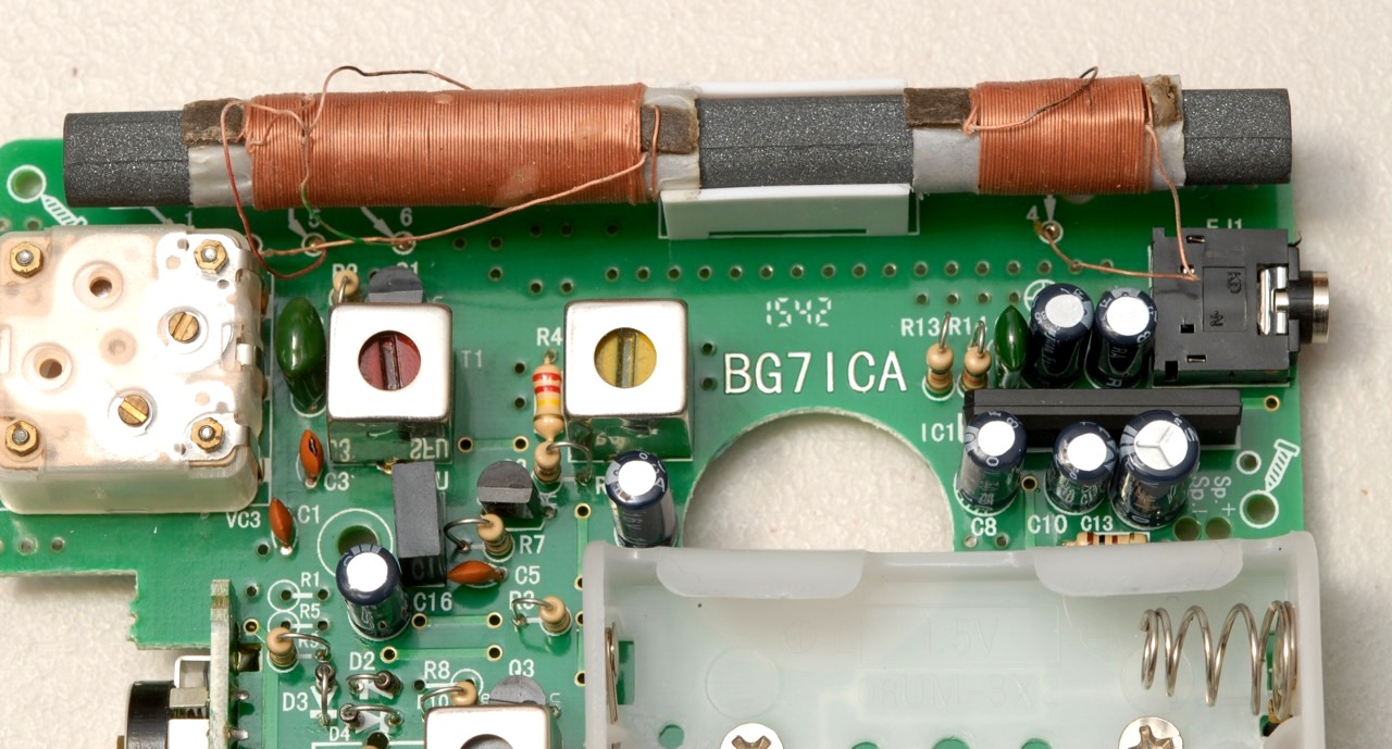
The antenna after installation.
I went back and installed R1, R5, and R8. I also installed the metal shield over the detector circuitry.
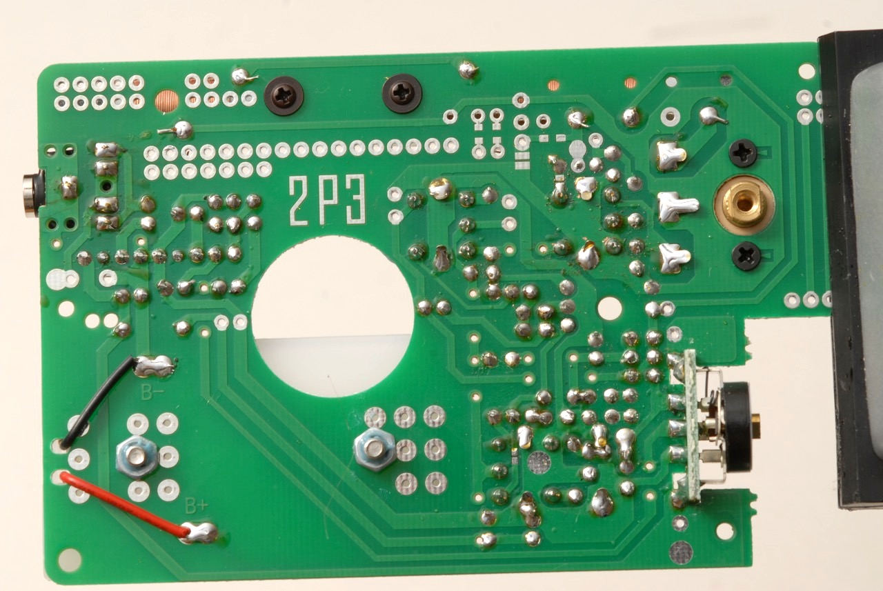
Here is the solder side of the fully populated board.
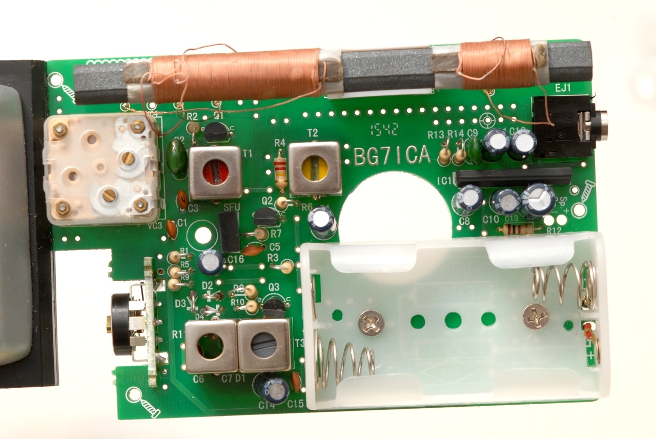
And here is the component side of the fully populated board.
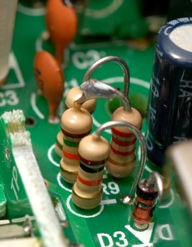
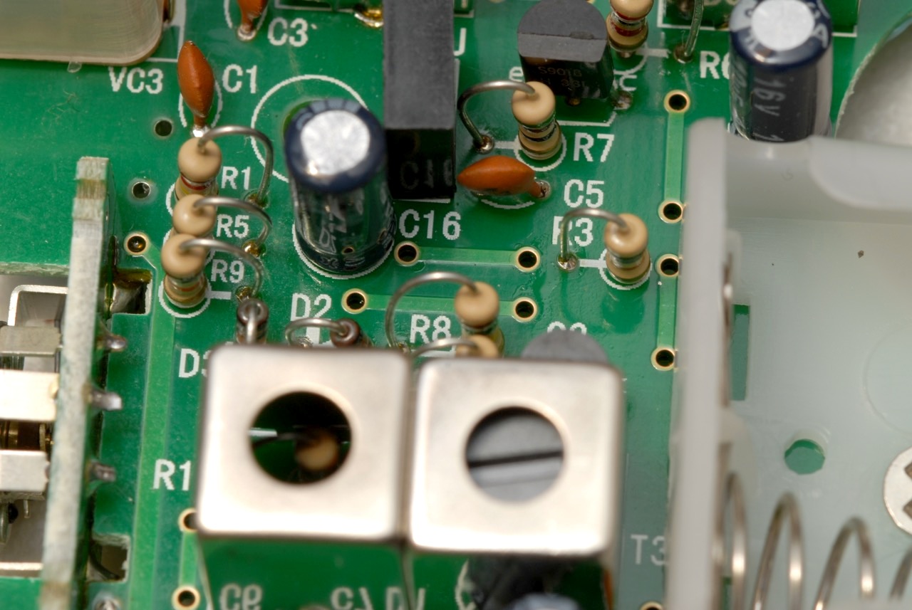
I checked the current at the three test points indicated in the instructions. Points 1 and 3 were well in the middle of the specified ranges, just right. But the second one was 0.3mA, right at the low end of the desired 0.3-0.6 mA range. I probably should have left it alone, but I wanted better, so I decided to swap out R5 and replace the nominal 18k value with the 15k resistor supplied in the kit, to increase the bias current a bit. But oops, that took the current too high, about 0.7mA. So I found a 2.2k resistor from my parts stash, and wired it in series with the 15k resistor, for around 17k. You can see the two resistors side-by-side in the center of this photo, joined at the top with a solder blob. It’s not the most beautiful solution, but it’s not too ugly, and it resulted in a bias of about 0.4mA, easily within the correct range.
Time for a break. Next time, we’ll go on to mechanical assembly.